Calculate RLC Parallel Circuit
Calculator and formulas for calculating voltage and power of an RLC parallel circuit
Calculate RLC Parallel Circuit
RLC Parallel Circuit
This function calculates power, current, impedance and reactance of a parallel circuit consisting of resistor, inductor and capacitor at a given frequency.
RLC Parallel Circuit
Parallel Circuit Properties
- Same voltage across all components
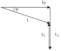
- Geometric addition of branch currents
- IL and IC are 180° out of phase
- Total current can be smaller than largest branch current
Basic Formulas
Current and admittance triangle according to Pythagoras
Admittances
- G: Conductance = 1/R
- BL: Inductive susceptance = 1/XL
- BC: Capacitive susceptance = 1/XC
- Y: Admittance = 1/Z
RLC Parallel Circuit - Theory and Formulas
Fundamentals of RLC Parallel Circuit
The total resistance of the RLC parallel circuit in the AC circuit is called impedance Z. Ohm's law applies to the complete circuit. The total current I is the sum of the geometrically added branch currents.
Current Triangle
Currents
Admittance Triangle
Reactances and Currents
Reactances
Frequency-dependent resistances of inductor and capacitor.
Branch Currents
All branches have the same voltage U.
Total Current
Geometric addition of branch currents.
Power Triangle
Powers
Phase Relationships
Phase Positions
- Resistor R: Current and voltage in phase
- Inductor L: Voltage leads current by +90°
- Capacitor C: Voltage lags current by -90°
- Resulting phase: Depends on IC - IL
Frequency Behavior
Low Frequencies
- XC >> XL
- IC << IL
- Inductive behavior
- Positive phase shift
Resonance Frequency
- IL = IC
- Z = R (maximum)
- φ = 0°
- Minimum total current
High Frequencies
- XL >> XC
- IL << IC
- Capacitive behavior
- Negative phase shift
Practical Applications
Filter circuits:
Tuned circuits:
Reactive power:
Differences to Series Circuit
Parallel vs. Series
Parallel circuit:
- Same voltage across all components
- Z maximum at resonance
- I minimum at resonance
- Current division according to impedance
Series circuit:
- Same current through all components
- Z minimum at resonance
- I maximum at resonance
- Voltage division according to impedance
Design Guidelines
Important Design Aspects
- Current division: Depends on frequency and component values
- Resonance: At f₀ = 1/(2π√LC), Z is maximum
- Current enhancement: IL and IC can significantly exceed I
- Losses: ESR of components reduces maximum impedance
- Loading: Additional parallel load reduces total impedance
- Quality factor: Q = R/(XL or XC) at resonance