Calculate RL Differentiator
Calculator and formulas for calculating an RL differentiator circuit
RL Differentiator Calculator
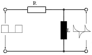
RL Differentiator Circuit
With this function, the properties of a differentiator circuit made from a resistor and an inductor can be calculated. The function calculates the inductor, resistance, or period/frequency.
Circuit Diagram & Signals
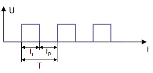
T = Period, t1 = Pulse
Operation
The differentiator functions as a pulse shaper stage. The RL circuit generates pulse-like AC voltage at the output from a square wave voltage at the input.
Time Constant
τ (Tau) determines the time behavior of the differentiator.
Example Calculations
Practical Calculation Examples
Example 1: Audio Pulse Generator
Given: L = 10 mH, R = 100 Ω, Pulse width t1 = 1 ms
Example 2: Digital Edge Detection
Given: L = 1 µH, Pulse width t1 = 100 ns, τ = 20 ns
Example 3: RF Pulse Generator
Given: R = 50 Ω, t1 = 10 ns, τ = 2 ns
Optimal Ratios
Pulse length to time constant:
Typical Applications:
RL Differentiator - Theory and Formulas
What is an RL Differentiator?
An RL differentiator is a pulse shaping circuit that generates short, needle-shaped pulses from square wave pulses. The output signal approximately corresponds to the mathematical derivative of the input signal. The time constant τ = L/R determines the properties of the pulse shaping.
Calculation Formulas
Time Constant and Basic Formulas
Time Constant
Determines the time behavior of the circuit
Calculate Resistance
Resistance for desired time constant
Calculate Inductance
Inductance for desired time constant
Transfer Function
Laplace transfer function
Pulse Ratios for Optimal Differentiation
5τ Rule
Basic rule for good differentiation
10τ Rule
Optimal differentiation with short pulses
Universal Formula
n = 5 for basic, n = 10 for optimal differentiation
Signal Behavior and Output Characteristics
Pulse Width (Output)
Width of output needle pulses
Amplitude (relative)
Height of output needle pulses
Pulse Behavior
- Positive edge: Positive output needle pulse
- Negative edge: Negative output needle pulse
- Constant voltage: No output signal
- Pulse duration: About 2-3 time constants
Design Rules and Optimization
Inductor Selection
- Low frequencies: mH range
- Audio/Digital: µH range
- RF/Pulse: nH range
- Quality: Use highest possible Q
Resistor Selection
- Impedance matching: Match to source/load
- Bandwidth: Smaller R = larger bandwidth
- Noise: Compromise between R and bandwidth
- Power rating: Sufficient power handling
Practical Applications
Signal Processing:
RF Technology:
Digital Technology:
Design Guidelines
Important Design Aspects
- Time constant: τ should be 5-10 times smaller than pulse width
- Bandwidth: f₃dB ≈ 1/(2πτ) - limits maximum operating frequency
- Impedance matching: R should match system impedance
- Parasitic effects: Consider inductor self-capacitance at high frequencies
- Saturation: Inductor core must not saturate at high currents
- Temperature: Consider temperature drift of L and R
Signal Behavior
Characteristic Properties
- Input signal: Square wave pulses with defined edges
- Output signal: Short needle pulses at each edge
- Positive edge: Positive output needle pulse
- Negative edge: Negative output needle pulse
- Pulse duration: About 2.2 time constants (10%-90% criterion)
- Amplitude: Depends on τ/t₁ ratio
|
|