Calculate RL High-pass Filter
Calculator and formulas for calculating the parameters of an RL high-pass filter
Calculate RL High-pass Filter
RL High-pass Filter
This function calculates the properties of a high-pass filter made from a resistor and an inductor. It calculates the output voltage, attenuation, and phase shift at the given frequency.
RL High-pass Filter
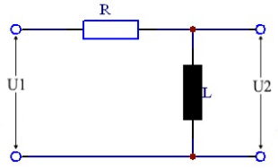
Parameters
Formulas for RL High-pass Filter
Calculate Voltage Ratio
The output voltage U2 of an RL high-pass filter is calculated using the following formula.
Output Voltage
or simpler, when XL is known:
Reactance
The inductive reactance increases proportionally with frequency.
Attenuation in Decibels
The attenuation is 3dB at the cutoff frequency. It can be calculated for different frequencies using the formulas below.
Attenuation (simple)
When input and output voltages are known.
Attenuation (complex)
Direct calculation from R, L and ω.
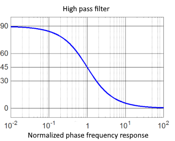
Phase Shift
In an RL high-pass filter, the output voltage leads the input voltage by 0° - 90° depending on frequency. At the cutoff frequency, the phase shift is 45°.
Phase angle (simple)
Phase angle (complex)
Cutoff Frequency
At cutoff frequency fc, the value of the amplitude-frequency response equals 0.707. This corresponds to –3dB.
Cutoff Frequency Formulas
Calculation Examples
Example 1: Output Voltage
Given: R = 10Ω, L = 2mH, f = 500Hz, U₁ = 10V
Result: Output voltage = 5.33V
Example 2: Cutoff Frequency
Given: R = 1kΩ, L = 100mH
Result: Cutoff frequency ≈ 1.59kHz
Example 3: Attenuation
Given: U₁ = 10V, U₂ = 7.07V
Result: Attenuation = -3dB (cutoff frequency)
Example 4: Phase Shift
Given: R = 100Ω, ω×L = 100Ω
Result: Phase shift = 45° (at cutoff frequency)
Practical Applications
Audio Technology
- Treble filters
- Crossover networks
- DC decoupling
- Rumble filters
Signal Processing
- Differentiator
- Edge enhancement
- AC coupling
- Noise filters
Measurement Technology
- Common mode rejection
- Offset filters
- High-frequency couplers
- Interference suppression
|
|