Calculate LED Series Resistor
Online calculator and formulas for calculating the resistor for an LED
LED Series Resistor Calculator
LED Parameters
LEDs require a series resistor for current limiting. Enter supply voltage, LED voltage and desired current.
LED Circuit
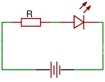
Circuit diagram: LED with series resistor
Basic Formulas
Symbol Legend
Practical Calculation Examples
Example 1: Red LED at 5V
Given: VS = 5V, VD = 2.0V, ID = 20mA
Step-by-Step Calculation
Practice: Next E12 value: 150Ω, resistor ≥ 1/8W
Example 2: Blue LED at 12V
Given: VS = 12V, VD = 3.2V, ID = 20mA
Step-by-Step Calculation
Practice: Next E12 value: 470Ω, resistor ≥ 1/4W
Example 3: White LED at 24V (Industrial Application)
Given: VS = 24V, VD = 3.4V, ID = 30mA
Detailed Analysis
Actual current: \[I = \frac{20.6V}{680Ω} = 30.3mA\]
Efficiency Comparison
Resistor Selection (E12 Series)
LED Theory and Applications
Operating Principle
LEDs (Light Emitting Diodes) are semiconductor diodes that emit light when current flows through them. Unlike incandescent bulbs, LEDs have a non-linear current-voltage characteristic and require current limiting for safe operation.
Why a Series Resistor?
- Current limiting: LEDs have a very steep current increase with small voltage increases
- Overcurrent protection: Without limiting, the LED would be destroyed by excessive current
- Voltage adaptation: Supply voltage is usually higher than LED forward voltage
- Temperature compensation: The resistor stabilizes current with temperature variations
LED Characteristics by Color
| Color | Forward Voltage | Typical Current | Wavelength | Material |
|---|---|---|---|---|
| Red | 1.8-2.2V | 10-20mA | 620-750nm | AlGaAs, GaAsP |
| Orange | 2.0-2.2V | 10-20mA | 590-620nm | GaAsP, AlGaInP |
| Yellow | 2.0-2.2V | 10-20mA | 570-590nm | GaAsP, AlGaInP |
| Green | 2.0-2.4V | 10-20mA | 520-570nm | GaP, AlGaInP, InGaN |
| Blue | 3.0-3.4V | 10-20mA | 450-520nm | InGaN, SiC |
| White | 3.0-3.6V | 15-25mA | 400-700nm | InGaN + Phosphor |
| Infrared | 1.2-1.4V | 10-50mA | 750-1000nm | GaAs, AlGaAs |
Important Notes
- Never operate LEDs without current limiting
- Observe polarity (anode = longer leg)
- Observe maximum current per datasheet
- Consider heat dissipation at high currents
- Observe ESD protection during handling
Practical Tips
- Use E12 series resistors
- Choose resistor ≥ 2× calculated power
- For series connection: use LEDs of same type
- At high voltages: consider constant current source
- For dimming: PWM instead of analog control
Advanced Circuits
- Constant current source: Better efficiency
- Switching regulator: High efficiency
- PWM dimmer: Brightness control
- Series connection: Multiple LEDs
- Matrix control: Many LEDs
Operating Multiple LEDs
Series Connection (recommended)
Parallel Connection (problematic)
Typical Applications
Lighting
Signals
Displays
Optics
|
|