Calculate Zener Diode Series Resistor
Calculate series resistor for a Zener diode with constant load
Zener Diode Series Resistor Calculator
Voltage Regulation
Calculation for constant load. The series resistor must limit and stabilize the total current (load + Zener diode).
Zener Diode Voltage Regulator
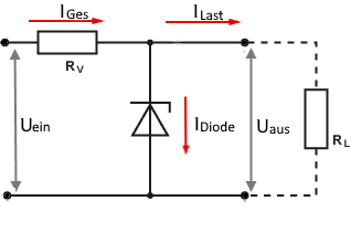
Circuit diagram: Zener diode with series resistor
Operating Principle
- Zener diode stabilizes the output voltage
- Constant total current through series resistor
- Current division between load and Zener diode
- Minimum current through Zener diode required
Important Notes
Basic Formulas
Practical Calculation Examples
Example 1: 5V Voltage Regulator
Given: Uin = 12V, UZ = 5.1V, IL = 100mA
Step-by-Step Calculation
Efficiency: η = 5.1V/12V = 42.5%
Example 2: 3.3V for Microcontroller
Given: Uin = 5V, UZ = 3.3V, IL = 50mA
Step-by-Step Calculation
Efficiency: η = 3.3V/5V = 66%
Example 3: 15V Reference Voltage (Precision Application)
Given: Uin = 24V, UZ = 15V, IL = 5mA (OpAmp reference)
Detailed Analysis for Precision Application
For precision: temperature compensation needed
Precision: For highest accuracy use reference IC (LM4040, etc.)
Zener Diode Component Selection
Design Guidelines
Theory and Applications of Zener Diode Voltage Regulation
Operating Principle
The Zener diode voltage regulator uses the constant breakdown voltage of a Zener diode for voltage stabilization. The series resistor limits the total current, while the Zener diode conducts excess current and keeps the output voltage constant.
Current Distribution
- Constant total current: Same current always flows through the series resistor
- Variable current distribution: Itotal = IL + IZ
- Stabilization: Zener diode compensates for load current variations
- Minimum current: Zener diode needs minimum current for stability
Mathematical Relationships
Total current:
Series resistor:
Resistor power dissipation:
Zener power dissipation:
Disadvantages
- Poor efficiency (30-70%)
- High power dissipation with large voltage differences
- Temperature dependence of Zener voltage
- Poor load regulation with large current variations
- Limited output currents
Advantages
- Simple design (only 2 components)
- Low cost
- Good voltage regulation
- Fast response to load changes
- Proven technology
Typical Applications
- Reference voltages: ADC, DAC, OpAmp
- Simple power supplies: Battery replacement
- Overvoltage protection: Parallel to load
- Voltage limiting: Signal processing
- Bias voltages: Amplifier circuits
Zener Diode Characteristics
| Voltage Range | Temperature Coefficient | Application | Special Features |
|---|---|---|---|
| 2.7V - 4.7V | Negative (~-2mV/°C) | Low voltage regulation | Temperature compensation needed |
| 5.1V - 6.8V | Minimal (~0mV/°C) | Reference voltages | Best temperature stability |
| 7.5V - 22V | Positive (+2mV/°C) | High voltage regulation | Higher power types available |
Design Considerations and Alternatives
When to use Zener diode regulator?
Better Alternatives
Symbol Legend
| Uin | Input voltage [V] |
| UZ | Zener voltage (output voltage) [V] |
| IL | Load current [A] |
| IZ | Zener current [A] |
| IZ,min | Minimum Zener current for stability [A] |
| Itotal | Total current through series resistor [A] |
| Rs | Series resistor [Ω] |
| PRs | Power dissipation in series resistor [W] |
| PZ | Power dissipation in Zener diode [W] |
|
|