T Attenuator
Calculator and formulas for calculating the resistances of a T attenuator
T Attenuator Calculator
Input Modes
Enter either the attenuation in dB or the voltage ratio U₁/U₂. The impedance must be specified for both modes.
T Attenuator
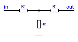
Circuit diagram of a T attenuator
Purpose and Application
- Impedance matching at high frequencies
- Input and output impedance equal to characteristic impedance
- Controlled signal attenuation without distortion
- T-shaped resistor arrangement
Input Modes
Important Note
Formulas for T Attenuator
Basic Formulas
The resistances R₁ and R₂ of the T attenuator are calculated from the impedance Z and the attenuation factor a. The attenuation factor a is calculated from the ratio of output voltage to input voltage (U₁ / U₂), or from the attenuation ΔL in dB.
Attenuation Factor
Ratio of input to output voltage
Series Resistance R₁
Resistances in the signal line
Parallel Resistance R₂
Resistance between the lines
Practical Calculation Examples
Example 1: 6dB attenuation at 50Ω
Given: Z = 50Ω, ΔL = 6dB
Standard 6dB attenuation for 50Ω systems
Example 2: 10dB attenuation at 75Ω
Given: Z = 75Ω, ΔL = 10dB
Typical attenuation for cable TV applications
Example 3: Voltage ratio at 600Ω
Given: Z = 600Ω, U₁ = 10V, U₂ = 2V
Classic audio technology with 600Ω impedance
Applications and Comparison with Pi Attenuator
Typical Applications
- RF measurement technology: Calibrated attenuation for measurements
- Antenna technology: Matching between transmitters and antennas
- Cable TV: Signal level attenuation in distribution systems
- Laboratory measurement: Defined signal attenuation
- EMC testing: Controlled signal reduction
- Audio measurement: Precise level attenuation
Comparison: T vs. Pi Attenuator
| Property | T Attenuator | Pi Attenuator |
|---|---|---|
| Structure | 2×R₁ in series, R₂ parallel | R₁ in series, 2×R₂ parallel |
| Impedance behavior | Lower impedance at high attenuation | Higher impedance at high attenuation |
| Application | Preferred for low-impedance systems | Preferred for high-impedance systems |
| Symmetry | Symmetrically constructed | Symmetrically constructed |
Advantages of T Attenuator
- Constant impedance matching
- Good broadband characteristics
- Symmetrical input and output impedance
- Lower parallel resistance at high attenuation
- Lower power dissipation in parallel resistance
Design Guidelines
- Use precision resistors (1% or better)
- Pay attention to power handling capability
- Minimize parasitic capacitances at RF
- Use short, symmetrical connections
- Consider temperature coefficients
Practical Tips
- Standard impedances: 50Ω (RF), 75Ω (Video), 600Ω (Audio)
- Attenuation values: 3dB, 6dB, 10dB, 20dB are common
- For high attenuation: Cascade multiple stages
- At very high frequencies: Use stripline technique
- Prefer T attenuator for low-impedance systems
Related Calculators
For alternative topology:
Pi AttenuatorFrequency Response and Application Limits
Frequency Dependence
The T attenuator shows good broadband behavior when correctly dimensioned. The cutoff frequency is mainly determined by parasitic reactances and component geometry.
Discrete resistors
Standard packages
SMD packages
Short connections
Stripline technique
Microwave design
Choice between T and Pi attenuator: T attenuators are particularly suitable for low-impedance systems, as the parallel resistance R₂ remains relatively low even at high attenuation.