Calculate Loaded Voltage Divider
Online calculator for calculating the values of a loaded voltage divider
Loaded Voltage Divider
Loading Effect
A load resistor RL parallel to R₂ changes the division ratio. Enter either the desired output voltage U₂ or the load resistance RL.
Loaded Voltage Divider
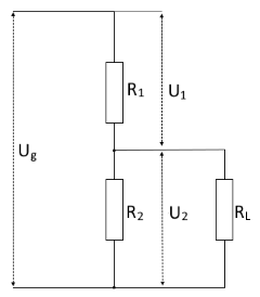
Circuit diagram: Loaded voltage divider with load resistance RL
Loading Effect
The load resistance RL parallel to R₂ changes:
- The voltage division ratio
- The output voltage U₂ (becomes smaller)
- The total current (becomes larger)
- The current distribution in the circuit
Main Formula
Important Note
Formulas for Loaded Voltage Divider
1. Calculate parallel resistance
Equivalent resistance of R₂ and RL:
Product formula for parallel connection
2. Output voltage
Modified voltage divider formula:
With parallel resistance R2L
3. Calculate currents
According to Ohm's law:
Additional formulas
Calculate load resistance from R2L:
Calculate R2L from voltages:
Practical Calculation Example
Example: Loading effect of a voltage divider
Given: Uin = 15V, R₁ = 10kΩ, R₂ = 20kΩ, RL = 30kΩ
Step 1: Unloaded voltage divider (reference)
Step 2: Calculate parallel resistance R₂ || RL
Step 3: Calculate loaded output voltage
Step 4: Calculate currents
Step 5: Evaluate loading effect
Current increase: 0.68mA vs. 0.5mA unloaded (36% increase)
Applications and Design Guidelines
Typical Applications
- Signal sources: Voltage dividers with changing loads
- Sensor interfaces: Adaptation to different input resistances
- ADC preamplifiers: Considering input impedance
- Audio circuits: Volume controls with headphone loads
- Measurement circuits: Voltage dividers with measuring device resistances
Design Guidelines
- Load factor: RL should be at least 10× larger than R₂
- Voltage regulation: For ±5% accuracy: RL ≥ 20 × R₂
- Current consumption: Voltage divider current >> Load current
- Buffering: Use operational amplifiers for high-impedance loads
Comparison with unloaded voltage divider
| Parameter | Unloaded | Loaded |
|---|---|---|
| Output voltage | Constant (ideal) | Reduced by load |
| Total current | Uin/(R₁+R₂) | Higher due to parallel resistance |
| Application | Reference voltages | Signal sources with load |
| Stability | Very good | Depends on RL |
Important Notes
- Load effect: Every connected load changes the output voltage
- Current consumption: Higher current consumption due to parallel load
- Temperature drift: All resistors affect stability
- Frequency response: Capacitive loads can cause instability
Related Calculators
For unloaded applications:
Unloaded Voltage DividerPractical Tips
- Use buffer amplifiers for variable loads
- Calculate worst-case scenarios
- Consider tolerances of all resistors
- Monitor power dissipation
Symbol Definitions
| Uin | Input voltage of the voltage divider |
| U₁ | Voltage across R₁ |
| U₂ | Output voltage across R₂ || RL |
| R₁, R₂ | Voltage divider resistances |
| RL | Load resistance parallel to R₂ |
| R2L | Parallel resistance of R₂ and RL |
| I₁, I₂, IL | Currents through the respective resistances |