Calculate Voltmeter Series Resistor
Calculator and formulas for calculating the series resistor of a voltmeter
Series Resistor Calculator
Measuring Range Extension
Calculation of the series resistor to extend the measuring range of a voltmeter. Choose between meter resistance or meter current as input parameter.
Voltmeter Series Resistor
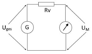
Circuit diagram: Voltmeter with series resistor
Purpose of Series Resistor
- Measuring range extension for voltmeters
- Voltage reduction for the meter movement
- Enables measurement of higher voltages
- Protection of the sensitive meter movement
Input Modes
Important Note
Formulas for Series Resistor Calculation
Calculation via Meter Current
When the meter current is known:
Voltage drop across series resistor ÷ meter current
Calculation via Meter Resistance
When the meter resistance is known:
Voltage ratio determines series resistor
Voltage Divider Principle
The series resistor and meter movement form a voltage divider:
Practical Calculation Example
Example: Measuring range extension from 10V to 100V
Given: Voltmeter with Rm = 10kΩ, Um = 10V, desired measuring range: 100V
Solution using voltage divider formula
The measuring range is successfully extended from 0-10V to 0-100V.
Calculation Verification
Practical Notes
Theory and Practical Applications
Operating Principle
A series resistor for a voltmeter is used to extend the maximum measurable range. The series resistor is connected in series with the voltmeter and forms a voltage divider with the internal resistance of the voltmeter.
Important Properties
- Voltage division: Input voltage is divided proportionally to the resistances
- Same current: The same current flows through both resistances
- Input resistance: Increases by the extension factor
- Linearity: Linear scaling of the measuring range
Practical Applications
- Digital multimeters: Voltage measurement in different ranges
- Analog instruments: Range extension of mechanical meter movements
- Oscilloscopes: Probe heads with 10:1 or 100:1 division
- Mains voltage measurement: Safety isolation through high resistances
- HV measurement technology: High voltage measurement with divider circuits
Symbol Directory
| Utotal | Total voltage / Input voltage |
| Um | Voltage across meter movement |
| Rm | Resistance of meter movement |
| Im | Current through meter movement |
| Rs | Value of series resistor |
| Ps | Power of series resistor |
Important Notes
- Series resistor must be precisely dimensioned
- Consider power handling of series resistor
- Temperature coefficient important for accuracy
- Input resistance increases proportionally
- Maintain safety distances for high voltage
Practical Tips
- Use precision resistors (1% or better)
- Pay attention to low temperature coefficient
- Choose sufficient voltage rating
- For RF: Consider inductance of resistor
- Perform regular calibration